
Within VCF Networking in v9.0 there are several types of networks which can be created by the VPC Admin when granted permission and resources by the Project Admin. That is, as long as there are sufficient resources allocated to the Project by the Enterprise Admin. Wait? What? Who the heck are all these people and where did they come from?
In this post we'll take a look at each "persona", figure out if we have enough desks for them, and then see how those networks types differ. Finally and arguably most usefully, we'll explore if, and how, each network type can connect to other parts of the SDDC and, to the outside world. Along the way, we'll see how their IP addresses are managed and probably find a NAT or two hiding in the shadows...
Introduction
VCF Networking is provided by VMware’s NSX. In fact, if you wanted to, you could log in to NSX Manager and configure your SDDC’s networking just as you’ve done in the past. That is, if you have the skills in both the Networking and NSX departments to be able to do so. One criticism we’ve heard is that the people needing to simply deploy apps had to raise tickets with the VI Admins and somebody had to then raise a ticket with the Network Admins just so the end user could get “some networking” to deploy their apps on. If things are working fine for you that way, that model is still present in VCF9 using vCenter and NSX Manager (as well as the physical network management tools of course) but VCF Networking aims to simplify that whole process.
What? You don't use NSX? 🤦
Not every SDDC uses NSX, and in those cases, the VI Admin would have to raise a ticket with the Network Admin asking for a “VLAN”, have it connected to the physical network interfaces of each ESXi host and then create a VLAN-backed dvPortGroup using the allocated VLAN ID. The introduction of NSX meant that the whole VLAN allocation malarkey could be done once to connect the hosts together, and then, each “new” network was defined in NSX without having to go back to the (physical/underlay) Network Admins each time.
NSX was designed to simplify the physical network configuration tasks, and the new VCF Networking model is designed to simplify that NSX model even further. The end goal being, of course, to minimize the time to value by getting those new projects deployed with the minimum of friction to the development teams.
Multi-Tenancy
In the Service Provider world, it is (pretty much) always necessary to provide separation between the “tenants” on a shared platform. Not only for privacy/security reasons, but also to remove the chance of configuration choices, like, for example, the same IP address ranges being made by multiple tenants creating conflicts in the underlying platform1. This “multi-tenancy” layer brings with it another layer of complexity, but can sometimes be useful, or necessary, even within a single Enterprise environment. As VMware folds the multi-tenant capabilities of VCD into VCF, users can make use of these Service Provider features to create more flexible, and arguably more secure, network topologies within VCF. Keep this in mind as you read on, where you’ll find confusing concepts like using the same IP addresses more than once in the same “network”.
Personas
Let’s take a brief look into the “roles” which VCF uses to segregate responsibilities in this new model. These are VCF constructs. If you work in a large organization where you have a similar separation of responsibilities, each role could be assumed by a different person. If you don’t operate in that way, some, or even all, of the roles can be assigned to the same person.
vCenter and the "Default" Project
Out of the box, VCF has a concept of a “Default” Project. This is created when NSX is deployed, and the resources within this project are accessible from vCenter. Choosing to work within this default Project enables the vCenter Admin to assume all of the roles of the different personas you will see mentioned below. This means, of course, that you don’t need to dive too deeply into these role separations unless it’s of benefit in your situation.
This VMware Blog Post talks about the Enterprise, Project and VPC Admin roles, and includes a diagram like this (which I shamelessly “borrowed” and then simplified) which shows how each of the roles’ influence/permissions are spread across the SDDC topology.
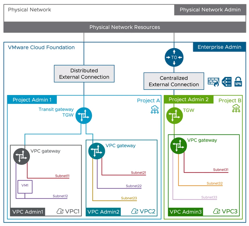 To confuse matters, you will also see references in the documentation to “Provider Administrator” and “Organization Administrator” which take the same admin separation in the picture above but expressed in Service Provider terminology where “Enterprise” equates to the (Service) “Provider”, and “Project” maps to the Service Provider’s customers which form the shared platform’s tenants or “Organizations”. You can read more about the SP (or commonly CSP) model in this TechDoc
Gateways, IP Blocks and Networks
If you look closely, the original diagram in the blog post shows everything we need to know about the different subnets types (which is the whole point of this post) and the “gateways” to which they connect. But don’t worry, you’re not getting that diagram as “homework” to figure out for yourself, we’ll look at each of the components in this section.
Peeling back the disguise.
The more curious of you might be wondering which of these components, once the Scooby Doo villain’s mask 👻 has been removed, is really just an NSX component in disguise. We won’t explore that here, you can take that away as homework if you want. If you’re an NSX guru already, you can probably work it out. If not, don’t worry, it’s probably not helpful to try and learn two new terms for each new thing. Let’s stick with what they’re called in the diagram, at least for now.
Reachability - Routing and Firewalls
Using firewall policies applied at the gateways (that we’ll look at next) or, if using vDefend distributed at the VM level, it is of course possible to stop traffic flows between any two points. Throughout this post we’ll use the terms reach, reachable and reachability to mean “unless there’s some firewall rule in the way, source A can reach destination B”.
Gateways
We’ll start with Gateways, as they form the boundaries that limit (or permit) where traffic from the different network types can flow to / reach. Knowing what each does will help us build a framework to hang the network types from. For reference, each gateway is typically created by the “Admin” at the level above when they create the containing entity (Project or VPC), but consumed / used by the Admin of the level where the gateway sits. Here’s a simplified slice of that earlier diagram.

Starting at the bottom and working upwards we have:
1. The VPC Gateway
- The VPC Gateway is created with the VPC by the Project Admin when they create the VPC. Networks/Subnets within each VPC are connected to their local VPC Gateway which provides connectivity between them. Every Subnet in a VPC can reach every other Subnet in the VPC.
- The VPC Admin can then create all the Subnets they need, which can be connected to their VPC Gateway allowing access to the rest of the VPC and beyond.
2. The Transit Gateway (TGW)
- The Transit Gateway is created (by the Enterprise Admin) within the Project at project creation time. The Transit Gateway is responsible for connecting the VPCs within a Project to each other, and, for aggregating North/South traffic into and out of the Project.
- It also handles “external connectivity” to physical upstream networks and connectivity. we’ll see more of that in the External Connectivity section a little later.
- The Enterprise Admin can expose one or more “External Connections” to the Project and the Project Admin can select the appropriate one to connect to the TGW to suit the Project’s external traffic requirements. The Project Admin has no access to the configuration of the External Connection other than choosing the one they want to use.
3. The Tier-0 (T0) Gateway
The T0 Gateway clearly did not get the memo about disguising its NSX origins. 🤦♂️ It provides the (centralized) connection between the Projects’ transit gateways and some form of external networking.
- The T0 Gateway is provisioned outside of the Project/Tenant view and is only visible through the options for External Connectivity which it provides and which are then exposed to the consumers below.
- Active/Standby T0’s with Active/Standby uplinks offer external connections with stateful services as those services are all concentrated on the active node at any time.
- Active/Active T0’s with ECMP uplinks offer a restricted set of services because there is no single point at which state can be established / maintained.
- The Enterprise Admin may have both types of T0’s deployed to be able to offer service-rich or higher-throughput External Connectivity options to the Projects/Tenants below.
IP Blocks
Now we have some structure, we’ll look at the way corporate IP addresses are presented to the SDDC, made available to the Projects and VPCs and see how far using each type will let us reach. Let’s see them laid out visually, then we’ll examine each in turn.

Again, as networks are always created within a VPC, that is where these IP addresses will be consumed when assigned to subnets, but the columns to the right of the diagram represent the scope of each IP block type. Let’s look at each type in turn.
1. External IP Blocks
External IP Blocks are created by the Enterprise Admin working with the Physical Network architects/admins. These are blocks of IP addresses allocated from the corporate enterprise address space solely for the use of resources within the SDDC. The will be reserved in any corporate IPAM system and routed into the VCF networking domain from the physical network. These form the sources of “public” addresses consumed within the SDDC.
Just how public?
It’s really important to understand that in this context, “public” refers to their reachability from anywhere within the corporate network, and their unique nature (no multiple uses in different Projects or VPCs). The VCF usage of the term public is not the same as the more common usage of “public address” to mean globally unique “Internet” addresses used to reach services from anywhere on the public Internet. So for absolute clarity, here, “public” means Enterprise-unique and directly reachable from the rest of the corporate network and not, “public Internet”.
Multiple external IP blocks can be created and routed to the VCF SDDC. The Enterprise Admin can then make one or more of those blocks available to Projects. The same external block can be exposed to multiple projects because address allocations made from them are recorded/reserved centrally to avoid duplicate allocations.
2. Project IP Blocks
Project IP Blocks are created, as you’ve probably guessed, by the Project Admin and exist at the level of the Project. These addresses are reachable from all VPCs within the Project, but they are not advertised beyond their local Transit Gateway. As the reachability of these addresses in limited to the scope of the Project, the same addresses could be used in multiple Projects. Traffic outside of the Transit Gateway should never have these Project IP addresses as its source or destination.
3. VPC IP Blocks
Taking what we just saw in (2) above, you can probably work out what VPC IP Blocks are. So, with a quick copy/edit/paste of the last section, they are blocks of IP addresses created by the VPC Admin and exist at the level of the VPC. These addresses are reachable from all subnets within the VPC, but are not advertised beyond their local VPC Gateway. As the reachability of these addresses is limited to the scope of the VPC, they could be used in multiple VPCs within any Project. Traffic outside of the local VPC Gateway should never have these VPC IP addresses as its source or destination.
Networks
Although it’s called out in the diagram, it’s worth mentioning here, the subnets below are always created within the context of a VPC and connected to a VPC Gateway, that bit doesn’t change. What changes between each is “where” the subnet’s address space comes from and how globally or locally unique it is. Let’s add some networks and devices to our diagram.

1. Public Subnets
Public Subnets are created within a VPC and connected to the VPC Gateway.2 Their next-hop (“default”) gateway will be the VPC Gateway and their IP addresses will be sourced from one of the External IP block(s) which has been assigned/exposed to the Project. As they use enterprise-unique addresses, they are reachable from the local VPC, other VPCs in the same Project, other Projects and anywhere else on the corporate network.
2. Private Subnets
Private Subnets are created within a VPC and connected to the VPC Gateway.3 Their next-hop (“default”) gateway will be the VPC Gateway and their IP addresses will be sourced from one of the VPC IP Blocks. As they use VPC-”local” addresses they will only be reachable from within their local VPC. You could think of Private Subnets as “VPC Local Subnets” due to the reachability of the IP addresses they use.
3. Transit Gateway Private Subnets
Transit Gateway Private (TGW-Private) Subnets are created within a VPC and connected to the VPC Gateway just like the other Subnet types (and unlike back in the NSX-v days when you could create a network connected directly to the Edge Gateway rather than the Distributed Logical Router). Their next-hop (“default”) gateway will be the VPC Gateway and their IP addresses will be sourced from one of the Project IP Blocks. As they use Project-”local” addresses they will only be reachable from within their local Project. Like the (VPC) Private Subnets above, you could think of these as “Project Local Subnets” due to the reachability of the IP addresses they use.
Extended Connectivity
Now we have a model for creating subnets with different levels of reachability, let’s look at how they can connect to the outside world. Hang on! Outside world? A moment ago we were saying that “the blah blah subnet is only reachable from with the local whatever”? Now we’re going to allow them to get out and see more of the world? 🤔
Of course, while many workloads only need some form of “local” connectivity most of the time, there will be occasions where they might need to connect further afield. This might be for operational reasons, like logging errors, checking for updates etc. or, it might be because they are the device on a limited network which performs an application gateway role presenting a service to the outside world.
If only there were some way of temporarily giving them use of an IP address with greater reachability… 🙉 Oh no, we’re reaching for NAT ? 🙈 Sadly yes, we’re reaching for NAT! 🙊 Let’s look at the different scenarios we can employ in cases where we need to break the confines of our non-public Subnets. These will fall into two groups. Specific VMs or workloads which need dedicated external access in both directions or, VMs or workloads which just need to connect outside of their normal address scope (but don’t require unsolicited external connections allowed in to them).
External IPs
External IPs provide that dedicated in/outbound access. They are 1:1 NATs which translate a VM’s local address to a dedicated Public IP Block address. The NAT is configured at the Gateway at the edge of the scope of the VMs locally assigned address, so:
- Private Subnet VMs’ External IPs are configured on the VPC Gateway and apply each VM’s dedicated Public IP to traffic to/from anywhere outside of the local VPC.
- TGW-Private Subnet VMs’ External IPs are configured on the Project’s Transit Gateway and apply each VM’s dedicated Public IP to traffic to/from anywhere outside of the local Project.

Outbound NAT
(Default) Outbound NAT is the solution to that second group of VMs. It is configured at the VPC or Project level and results in a single dedicated Public IP address being assigned per-VPC / Project which is used to Source NAT (SNAT) any traffic leaving the subnet’s local scope. As with the External IPs this means:
- Private Subnet VMs’ traffic will have Source NAT applied using the VPC dedicated public IP address on the VPC Gateway itself, for all traffic leaving the VPC.
- TGW-Private Subnet VMs’ traffic will have Source NAT applied, using a project dedicated public IP address, this time on the Transit Gateway for all traffic leaving the Project.
Which, in another blatant example of copy, edit a little and then paste looks like this:

So, if the VMs in the diagram did not have 1:1 “External IP” NATs from the previous section, and were simply using SNAT for outbound access;
- VM 2 on the (VPC) Private Subnet would use the “VPC SNAT” configured on the VPC Gateway
- VM 3 on the TGW-Private Subnet would use the “TGW SNAT” configured on the Transit GW.
These Source NATs are “stateful” services, so will require both the VPC and Transit Gateways hosting the SNATs to also be stateful and hence run on an Active/Standby Edge cluster. This means if either gateway is active/active or distributed, the Default Outbound NAT option will not be available. We’ll see these options explored in slightly more detail in the next section.
External Connectivity
External connectivity is configured by the Enterprise Admin in cooperation with the physical network admin and defines the connection routes into the SDDC from the physical network and the nature of the gateway which connects the external network into the SDDC. The Enterprise Admin can configure multiple external connections, each with one or more External IP Blocks, which are connected to one of three types of gateways. These can then be exposed to one or more Projects (or Tenants in the Service Provider model).
That very first diagram showed a “Distributed” and a “Centralized” External Connection.
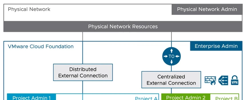
We’ll look at each in turn and, through necessity, peel back the villain’s disguise to see who they really are. We’ll start right to left with the Centralized one as that’s likely to be a more familiar concept to most of us.
Centralized External Connection
This is based upon the NSX Tier-0 router’s “Service Routing” component running on Edge Nodes (hence “centralized”), which terminates the external connectivity. Each Transit Gateway instantiated against this shared connection creates a T0 VRF instance which forms the service and routing components of the TGW.
The Tier-0 SR component can be configured as Active/Standby or, Active/Active. Any TGWs which are created using a given Centralized connection will assume the service model (A/S or A/A) of the connection’s parent Tier-0.
In a multi-tenant or highly segregated environment, a Tier-0 and its associated physical network uplink could be dedicated to a single Project / Tenant and present a dedicated uplink connection to a specific remote network.
Distributed External Connection
This is a new construct in VCF Networking (NSX) v9.0. It uses a physical network VLAN presented to each host to provide a Transit Gateway based upon a “Distributed Routing” component on each host. The next-hop gateway is on the upstream physical network gateway router, and this type of gateway can be configured without the need for Edge VMs.
"three types of gateways"?
If you were wondering where the “three types of gateways” three came from, it is:
- Centralized Active / Standby
- Centralized Active / Active
- Distributed.
Even through the two centralized options look similar, the loss of stateful services in Active/Active mode means a big change in available functionality to Projects utilizing this external connectivity type.
Conclusions / Wrap-up
If you come from an enterprise networking background this might seem a massive diversion from the NSX topologies of old. However, if you come from a Service Provider background, particularly where your tenants are allowed to bring their own IP address ranges, the concepts should be more familiar. If you have any experience of networking in, particularly hyper-scale, public clouds, many of the terms which have been adopted will seem familiar too.
VCF 9.0 networking will abstract away much of the complexity you’d expect to see when setting something like this up, allowing the personas we saw earlier to get on with what they need, without having to understand how it gets configured, or having to resort to calling in favors from their networking colleagues. In doing so, VCF 9.0 makes it so much easier to introduce NAT all over the place, which is, err… nice. 🤔 Now, where did I put my “Route if you can, (only) NAT if you (absolutely) must” T-shirt…
Oh, one last point, as you saw in the introduction and, at the time of writing, this approach is still optional and you can still stick with the familiar Tier-0 / Tier-1 model of NSX <9.0 if you prefer. So, if you’re feeling slightly ill after reading all this, you can take that as a bright side, at least for now.
References
Here are the public resources that were used in preparing this post which you can access directly if you’d like to learn more.
- VMware Blogs: “VCF 9.0: - A new era of Private Cloud networking”
- Broadcom Techdocs: “Provider Admin vs Organization Admin”
Footnotes
-
If you want to read (far) more (than is healthy) about this issue, check out this series of posts! ↩
-
Public Subnets are usually designed to be reachable from anywhere on the corporate network. They would usually be connected to their “default gateway” (the VPC Gateway) but could if required be left isolated. This may be to provide a local “cluster” or interconnect network which is isolated from the rest of the network, but still requires organizationally unique “public” addresses. ↩
-
Private Subnets are usually designed to be reachable from anywhere in the local VPC. They would usually be connected to their “default gateway” (the VPC Gateway) but could if required be left isolated. This may be to provide a local “cluster” or interconnect network which is isolated from the rest of the network, but still requires VPC “locally-unique” addresses. ↩