
In Part 1 of this series we introduced the Route-Based VPN. Here in Part 2 we’ll look at the deployment steps for the NSX-V Edge. Because a likely use case for this is to connect an on-premises NSX-V environment to a VMC SDDC, we’ll touch on the setup for the VMC end too [Spoiler Alert].
So, before we move on to the good stuff, let’s briefly recap. Policy-Based VPNs have to have the networks they are to VPN between configured in their policies. If the network world changes, the policies have to be changed too, or whatever has changed is ignored. Route-Based VPNs use a routing protocol (BGP) to tell their peer what networks they can reach, and then both use that information to configure which traffic should be sent through the VPN. When a VPN device learns of new networks, or old ones which are no longer reachable, it will tell it’s remote peer which will amend its VPN configuration to match the new topology.
Okay, let’s get started…
Contents
Route-Based VPN Setup
In this example we’ll look at a Route-Based VPN setup between a VMC SDDC (running, NSX-T under the covers) and our local NSX-V Edge.
This requires NSX-V v6.4.2 or greater! Unfortunately, if you're running NSX-V 6.4.1 or earlier I'm afraid you won't be able to create Route-Based VPNs (or L2VPN over IPSec, which also depend upon Route-Based VPN).
The VMware Cloud on AWS end
Setting up the VMC end isn’t that difficult. Much like the policy-based VPN, we just have to fill in the boxes, click save and we are, (in the immortal words of Jon Bon Jovi) “half way there”.
Here is the overview of our target SDDC. You can click the images for the full-sized versions. Its “VPN Public IP” is highlighted in the red oval, we’ll need this later on.
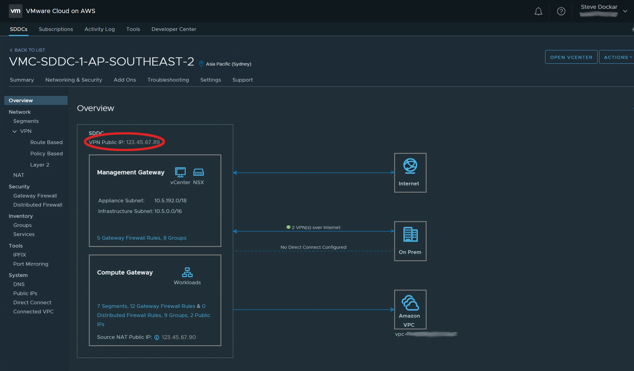
In NSX-T terms, that VPN Public IP is on the T0 router, and the Management and Compute Gateways are on T1 routers. Of course VMC hides that away so you don’t need to worry. Moving on, below, you can see the Route-Based VPN configuration screen.
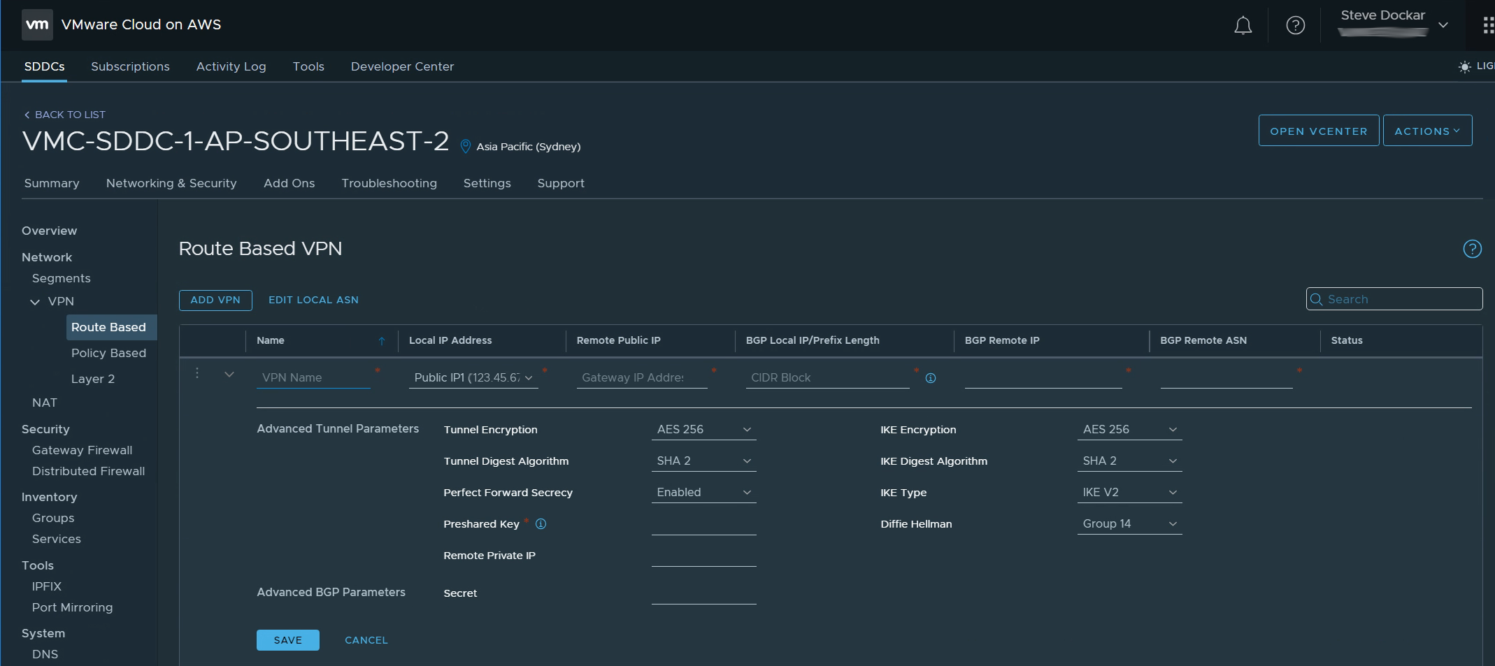
There’s not too much to fill in here. We need to provide;
- A name for this VPN.
- The (auto-populated) local public IP address.
- The public IP address of the remote VPN gateway (the NSX-V Edge in our example).
- The BGP Local IP/Prefix. This cleverly combines the VTI network, subnet mask and the IP address of our local VTI (see the diagram in Part 1), in one field.
- The IP address of the remote VTI.
- The BGP ASN of the remote network.
Then, below the line, the encryption parameters for the tunnel, key exchange parameters etc. and the Pre-Shared Key we’ll use. There are other parameters that aren’t editable from the VMC Console. Have a look at the VMC docs if you’d like to know more about those.
The NSX-V end
Moving to the NSX-V end things get a little more complex. When the NSX-V GUI was originally designed, the only Layer 3 VPNs we needed to configure where Policy-Based. The GUI is nicely layed out to show all the key details of those. Here is a view of the Policy VPNs we have configured.
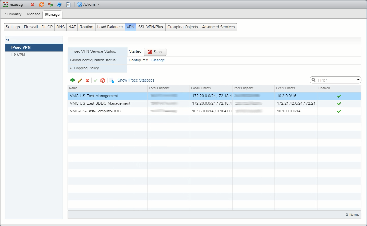
But, when we add the Route-Based VPNs things don’t look quite right. Check in the red ovals…
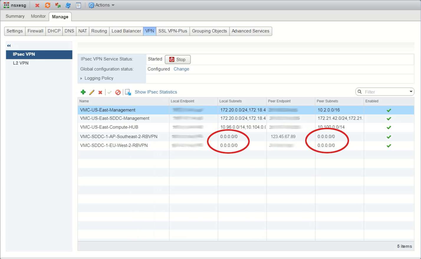
With Policy-Based VPNs we see the local and remote subnets (networks) that were configured when we set up the VPNs, but with Route-Based ones we’re only seeing 0.0.0.0/0. Network people will recognize that as the Default Originate or “all zeroes” route, but here it’s used to show that the Edge doesn’t know what routes are in the tunnel, to see that, we have to go look in the Routing -> BGP screen.
Before we do that, let’s have a look at the configuration of one of those Route-Based VPNs. As usual with Flex UIs we select the row and then click on the pencil icon…
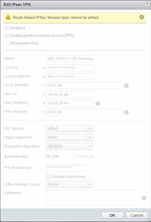
Uh ohh… That doesn’t look good. That yellow label does not bode well. We can’t edit a Route-Based session (VPN)? Let’s have a look at the docs…
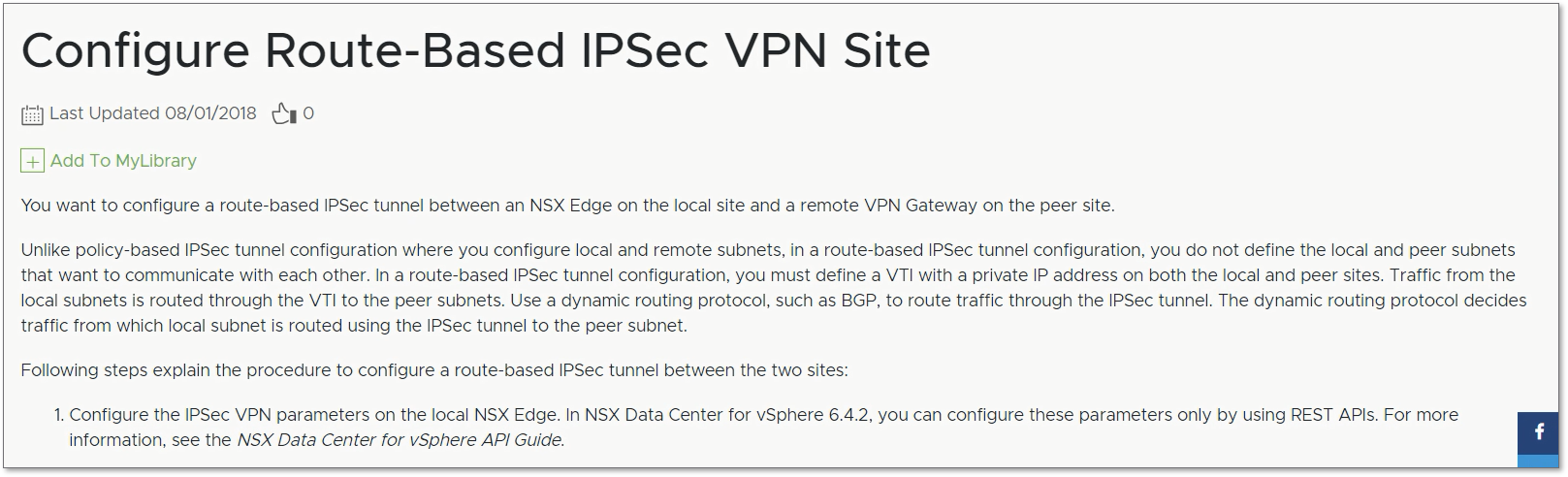
It’s a bit small, but the answer is in the bottom left of the image in the “1.” line (and on page 260 if you download the PDF version). Evidently, “you can configure these parameters only by using REST APIs”. Right, let’s break out the API wrangling gear…
First though, we probably need to have a look at the API guide. Way down in the unfashionable western spiral arm of the guide, (on page 491), we see the start of our API journey.
GET /api/4.0/edges/{edgeId}/ipsec/configThere’s more information just before that point (starting on p488) that you can read for additional background if you want, but the gist of the process is this.
Configuration steps
- Use the API to GET the current ipsec configs for Edge {edgeID}.
- Add in the details for the new session (VPN) to the body of the response we got in Step 1, to the body of a new request.
- PUT the new request from Step 2.
- (optionally, cross fingers and hope for a 2xx response to Step 3!)
There are a couple of caveats that I’ll call out as we go through the steps, to save you the frustration of having to figure them out through trial and error-message deciphering. I’ll be using Postman for this part of the process but if you prefer to use something else that can make the API calls like curl, PowerShell, Python etc. feel free to adapt what you find here.
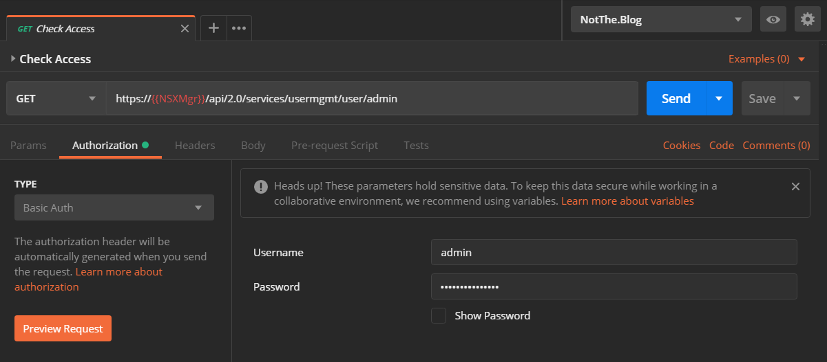
First, let’s ensure we have access to the NSX manager using:
GET https://{{NSXMgr}}/api/2.0/services/usermgmt/user/adminThe {{NSXMgr}} text is a Postman variable. This allows us to use this and the other API calls in the collection on different NSX deployments by swapping the variables’ contents stored in Postman’s “environments”. In this case {{NSXMgr}} holds the IP Address/FQDN of our test NSX Manager. We’ll also need to authenticate the request so we use the Authorization tab, select “Basic Auth” in the TYPE field and add our Username/Password so the request looks like this.
If all goes well when we hit the big blue Send button we’ll be rewarded with a “200 OK” response in the bottom of the Postman window which looks like this.
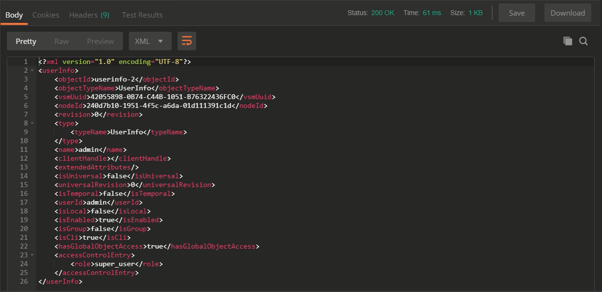
We did indeed get the Status 200, and line 17 shows us we authenticated as the “admin” user, so we’re all set!
Get the current IPSec VPN Config
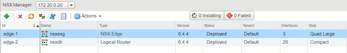
Onto the actually useful stuff… To start with we’ll need to GET the current VPN “ipsec/config” with that first API call we saw earlier, and for that we’ll need the {edgeID} to put into the call. We could use the API to get a list of Edges, but as we have access to the NSX Manager, let’s use the GUI. Here’s the list of Edges we have deployed and there are only two. “edge-2” is the Distributed Logical Router, and “edge-1” is our Edge Services Gateway.
So, adding that into our call (I have it stored in the {{Edge-ID}} variable), we can use the following to get the edge’s current IPSec config.
GET https://{{NSXMgr}}/api/4.0/edges/{{Edge-ID}}/ipsec/configAdding an entry to the Params section with a KEY of “showSensitiveData” and a VALUE of “true” will get the call to return, well, sensitive data… like err.. Pre Shared Keys, which is useful if you want to see what is configured, but should obviously be used wisely. Here’s that call in Postman with the optional Param added.

And if all goes well, we’ll see another “200 OK” result, and the top of a big blob of XML in the Body window, like this.
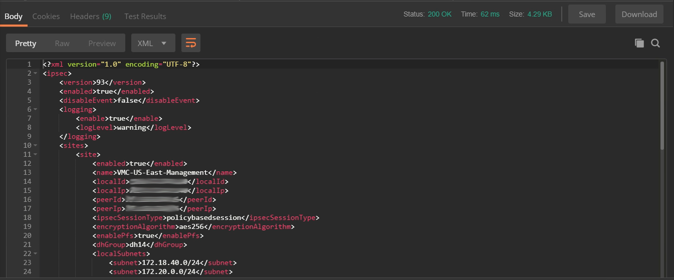
Let’s have a closer look at that XML body. Structurally it looks like this (the highlights are just comments to try and make it clearer and not part of the response).
 1<?xml version="1.0" encoding="UTF-8"?>
 2<ipsec>
 3    [ First some general heading stuff ]
 4    <version>93</version>
 5    <enabled>true</enabled>
 6    <disableEvent>false</disableEvent>
 7    <logging>
 8        <enable>true</enable>
 9        <logLevel>warning</logLevel>
10    </logging>
11    [ Next the sites collection/array/group ]
12    <sites>
13        [ Then the sites themselves ]
14        <site>
15            [ First site details ]
16        </site>
17        <site>
18            [ Second site details ]
19        </site>
20        [...]
21        <site>
22            [ Last site details]
23        </site>
24    </sites>
25    [ Finally, some 'global' parameters ]
26    <global>
27        <psk>NotTheRealPSK</psk>
28        <caCertificates/>
29        <crlCertificates/>
30    </global>
31</ipsec>
Now here’s the complete body of the response we got back. I’ve highlighted the details for one of our existing Route-Based VPN sites (lines 36-65), and we’ll use that as a template for the new site in a moment. If you don’t have a Route-Based VPN site you can copy yet, feel free to start with this one, or grab the template from the example response shown in the official NSX API docs page on VMware code.
  1<?xml version="1.0" encoding="UTF-8"?>
  2<ipsec>
  3    <version>93</version>
  4    <enabled>true</enabled>
  5    <disableEvent>false</disableEvent>
  6    <logging>
  7        <enable>true</enable>
  8        <logLevel>warning</logLevel>
  9    </logging>
 10    <sites>
 11        <site>
 12            <enabled>true</enabled>
 13            <name>VMC-US-East-Management</name>
 14            <localId>111.222.33.44</localId>
 15            <localIp>111.222.33.44</localIp>
 16            <peerId>44.55.66.77</peerId>
 17            <peerIp>44.55.66.77</peerIp>
 18            <ipsecSessionType>policybasedsession</ipsecSessionType>
 19            <encryptionAlgorithm>aes256</encryptionAlgorithm>
 20            <enablePfs>true</enablePfs>
 21            <dhGroup>dh14</dhGroup>
 22            <localSubnets>
 23                <subnet>172.18.40.0/24</subnet>
 24                <subnet>172.20.0.0/24</subnet>
 25            </localSubnets>
 26            <peerSubnets>
 27                <subnet>10.2.0.0/16</subnet>
 28            </peerSubnets>
 29            <psk>NotTheRealPSK</psk>
 30            <authenticationMode>psk</authenticationMode>
 31            <siteId>ipsecsite-1</siteId>
 32            <ikeOption>ikev2</ikeOption>
 33            <digestAlgorithm>sha1</digestAlgorithm>
 34            <responderOnly>false</responderOnly>
 35        </site>
 36        <site>
 37            <enabled>true</enabled>
 38            <name>VMC-SDDC-1-EU-West-2-RBVPN</name>
 39            <description>Route-based VPN to VMC-London</description>
 40            <localId>111.222.33.44</localId>
 41            <localIp>111.222.33.44</localIp>
 42            <peerId>22.33.44.55</peerId>
 43            <peerIp>22.33.44.55</peerIp>
 44            <ipsecSessionType>routebasedsession</ipsecSessionType>
 45            <tunnelInterface>
 46                <label>vti-1</label>
 47                <ipAddress>169.254.113.1/30</ipAddress>
 48                <mtu>1416</mtu>
 49            </tunnelInterface>
 50            <encryptionAlgorithm>aes256</encryptionAlgorithm>
 51            <enablePfs>true</enablePfs>
 52            <dhGroup>dh14</dhGroup>
 53            <localSubnets>
 54                <subnet>0.0.0.0/0</subnet>
 55            </localSubnets>
 56            <peerSubnets>
 57                <subnet>0.0.0.0/0</subnet>
 58            </peerSubnets>
 59            <psk>NotTheRealPSK</psk>
 60            <authenticationMode>psk</authenticationMode>
 61            <siteId>ipsecsite-29</siteId>
 62            <ikeOption>ikev2</ikeOption>
 63            <digestAlgorithm>sha1</digestAlgorithm>
 64            <responderOnly>false</responderOnly>
 65        </site>
 66        <site>
 67            <enabled>true</enabled>
 68            <name>VMC-SDDC-1-AP-Southeast-2-RBVPN</name>
 69            <description>Route-based VPN to VMC-Sydney</description>
 70            <localId>111.222.33.44</localId>
 71            <localIp>111.222.33.44</localIp>
 72            <peerId>33.44.55.66</peerId>
 73            <peerIp>33.44.55.66</peerIp>
 74            <ipsecSessionType>routebasedsession</ipsecSessionType>
 75            <tunnelInterface>
 76                <label>vti-2</label>
 77                <ipAddress>169.254.113.5/30</ipAddress>
 78                <mtu>1416</mtu>
 79            </tunnelInterface>
 80            <encryptionAlgorithm>aes256</encryptionAlgorithm>
 81            <enablePfs>true</enablePfs>
 82            <dhGroup>dh14</dhGroup>
 83            <localSubnets>
 84                <subnet>0.0.0.0/0</subnet>
 85            </localSubnets>
 86            <peerSubnets>
 87                <subnet>0.0.0.0/0</subnet>
 88            </peerSubnets>
 89            <psk>NotTheRealPSK</psk>
 90            <authenticationMode>psk</authenticationMode>
 91            <siteId>ipsecsite-30</siteId>
 92            <ikeOption>ikev2</ikeOption>
 93            <digestAlgorithm>sha1</digestAlgorithm>
 94            <responderOnly>false</responderOnly>
 95        </site>
 96        <site>
 97            <enabled>true</enabled>
 98            <name>VMC-US-East-SDDC-Management</name>
 99            <localId>111.222.33.44</localId>
100            <localIp>111.222.33.44</localIp>
101            <peerId>66.77.88.99</peerId>
102            <peerIp>66.77.88.99</peerIp>
103            <ipsecSessionType>policybasedsession</ipsecSessionType>
104            <encryptionAlgorithm>aes256</encryptionAlgorithm>
105            <enablePfs>true</enablePfs>
106            <dhGroup>dh14</dhGroup>
107            <localSubnets>
108                <subnet>172.18.40.0/24</subnet>
109                <subnet>172.20.0.0/24</subnet>
110            </localSubnets>
111            <peerSubnets>
112                <subnet>172.21.42.0/24</subnet>
113                <subnet>172.21.2.0/24</subnet>
114            </peerSubnets>
115            <psk>NotTheRealPSK</psk>
116            <authenticationMode>psk</authenticationMode>
117            <siteId>ipsecsite-3</siteId>
118            <ikeOption>ikev2</ikeOption>
119            <digestAlgorithm>sha1</digestAlgorithm>
120            <responderOnly>false</responderOnly>
121        </site>
122        <site>
123            <enabled>true</enabled>
124            <name>VMC-US-East-Compute-HUB</name>
125            <localId>111.222.33.44</localId>
126            <localIp>111.222.33.44</localIp>
127            <peerId>77.88.99.100</peerId>
128            <peerIp>77.88.99.100</peerIp>
129            <ipsecSessionType>policybasedsession</ipsecSessionType>
130            <encryptionAlgorithm>aes256</encryptionAlgorithm>
131            <enablePfs>true</enablePfs>
132            <dhGroup>dh14</dhGroup>
133            <localSubnets>
134                <subnet>10.96.0.0/14</subnet>
135                <subnet>10.104.0.0/14</subnet>
136                <subnet>10.112.0.0/14</subnet>
137            </localSubnets>
138            <peerSubnets>
139                <subnet>10.100.0.0/14</subnet>
140            </peerSubnets>
141            <psk>NotTheRealPSK</psk>
142            <authenticationMode>psk</authenticationMode>
143            <siteId>ipsecsite-4</siteId>
144            <ikeOption>ikev2</ikeOption>
145            <digestAlgorithm>sha1</digestAlgorithm>
146            <responderOnly>false</responderOnly>
147        </site>
148    </sites>
149    <global>
150        <psk>NotTheRealPSK</psk>
151        <caCertificates/>
152        <crlCertificates/>
153    </global>
154</ipsec>
Create the new site XML data
Here’s the “EU-West”
- <name>
- <description>
- <peerId>
- <peerIp>
- <tunnelInterface> -> <ipAddress>
- <psk>
<site>
    <enabled>true</enabled>
    <name>New-Site-RBVPN</name>
    <description>Route-based VPN to New Site</description>
    <localId>111.222.33.44</localId>
    <localIp>111.222.33.44</localIp>
    <peerId>123.45.67.89</peerId>
    <peerIp>123.45.67.89</peerIp>
    <ipsecSessionType>routebasedsession</ipsecSessionType>
    <tunnelInterface>
        <label>vti-3</label>
        <ipAddress>169.254.113.13/30</ipAddress>
        <mtu>1416</mtu>
    </tunnelInterface>
    <encryptionAlgorithm>aes256</encryptionAlgorithm>
    <enablePfs>true</enablePfs>
    <dhGroup>dh14</dhGroup>
    <localSubnets>
        <subnet>0.0.0.0/0</subnet>
    </localSubnets>
    <peerSubnets>
        <subnet>0.0.0.0/0</subnet>
    </peerSubnets>
    <psk>New-Site-PSK</psk>
    <authenticationMode>psk</authenticationMode>
    <siteId>ipsecsite-31</siteId>
    <ikeOption>ikev2</ikeOption>
    <digestAlgorithm>sha1</digestAlgorithm>
    <responderOnly>false</responderOnly>
</site>
Caveats and Gotchas
You may be wondering why a couple of items which sound like they should be unique (and therefor should be changed) aren’t highlighted. I wanted to call these out separately, as they’re the caveats I mentioned earlier which caught me out first time around. We will need a new <label> value for the <tunnelInterface>, and we’ll also need a new <siteId>. As an architect I like to layout a schema for things like address ranges, names etc, so I changed the <label> to “vti-[next-free-number]” (vti-3 in this case) and was rewarded with this:
<?xml version="1.0" encoding="UTF-8"?>
<error>
    <errorCode>13651</errorCode>
    <details>[Ipsec] Tunnel labels are managed by system. They are auto-generated for new sites and cannot be modified for existing sites.</details>
    <moduleName>vShield Edge</moduleName>
</error>
Okay, NSX doesn’t trust me to manage names… The solution? Just remove that line from our new body data. Done!
I also changed the <siteId> to “ipsecsite-[next-free-number]” (ipsecsite-31 in this case) and was then rewarded with this:
<?xml version="1.0" encoding="UTF-8"?>
<error>
    <errorCode>202</errorCode>
    <details>The requested object : ipsecsite-31 could not be found. Object identifiers are case sensitive.</details>
    <moduleName>core-services</moduleName>
</error>
Here we can see that if you include a <siteId> NSX presumes you’re changing that existing site, which we’re not, and so “ipsecsite-31 could not be found” makes sense. The solution? Once again, remove the field from the body and let NSX assign that value. Done!
With these corrections made, our new <site> XML looks like this:
<site>
    <enabled>true</enabled>
    <name>New-Site-RBVPN</name>
    <description>Route-based VPN to New Site</description>
    <localId>111.222.33.44</localId>
    <localIp>111.222.33.44</localIp>
    <peerId>123.45.67.89</peerId>
    <peerIp>123.45.67.89</peerIp>
    <ipsecSessionType>routebasedsession</ipsecSessionType>
    <tunnelInterface>
        <ipAddress>169.254.113.13/30</ipAddress>
        <mtu>1416</mtu>
    </tunnelInterface>
    <encryptionAlgorithm>aes256</encryptionAlgorithm>
    <enablePfs>true</enablePfs>
    <dhGroup>dh14</dhGroup>
    <localSubnets>
        <subnet>0.0.0.0/0</subnet>
    </localSubnets>
    <peerSubnets>
        <subnet>0.0.0.0/0</subnet>
    </peerSubnets>
    <psk>New-Site-PSK</psk>
    <authenticationMode>psk</authenticationMode>
    <ikeOption>ikev2</ikeOption>
    <digestAlgorithm>sha1</digestAlgorithm>
    <responderOnly>false</responderOnly>
</site>
As a side note, I'm pretty sure that when I tried this originally, after inserting my new <site> XML I incremented the <version>NN<version> ('93' in line 3 of the example above) as I would do in something like a DNS zone file and that also caused an issue. While grabbing some screenshots for this post I left the old version in, expecting an error, but instead the PUT completed successfully. It seems that either sending back the current version or, removing that line altogether both result in NSX happily incrementing the version number itself.
Tunnel Interface Addressing
The address we used in the <tunnelInterface>-><ipAddress> fields come from the link-local (sometimes known as APIPA) range reserved by IANA and described in rfc3927. When setting up a Route-Based VPN on VMC, the console suggests that you use a range of 169.254.x.x addresses for the VTI network. We could use any size with enough addresses, and I generally like to leave expansion room, but there’s virtually no chance we’ll need to add other devices to these networks so a /30 (two readily useable addresses) is plenty. VMC also helps by warning about a part of that 169.254 range which you should avoid, and then, if you pick another range it doesn’t like, VMC rewards you with a nice error message. I used a pseudo random generator to select the third octet and landed on 113. I then allocated a list of /30’s from which to assign to each Route-Based VPN’s VTI network in our global environment.
Hopefully, if you’re building Route-Based VPNs (or any VPN for that matter), you’re familiar with Subnets and Subnetting, but to aid with the examples here, each /30 network contains four addresses. The Network Address, two readily useable addresses, and the Broadcast Address on the end. Starting at 169.254.113.0, our first network has .0 (Network), .1 (useable), .2 (useable) and .3 (Broadcast). So, if Bold means useable, the first few networks are:
- 169.254.113.0 /30 - 0,1,2,3
- 169.254.113.4 /30 - 4,5,6,7
- 169.254.113.8 /30 - 8,9,10,11
- 169.254.113.12 /30 - 12,13,14,15 and so on…
Hopefully from this you can see how we got to the addresses in the code snippets and screen shots.
Creating the new VPN site
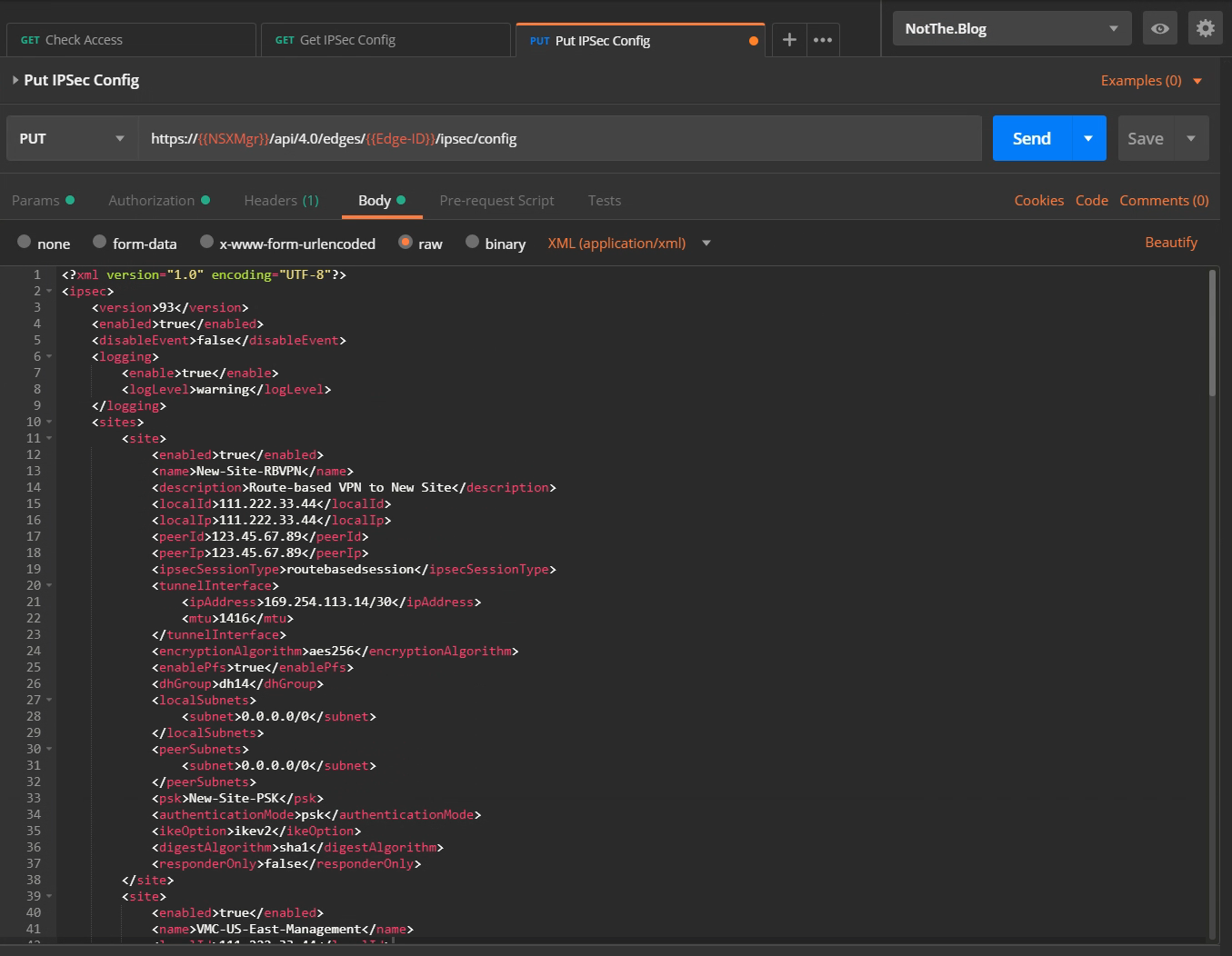
Right, we’re nearly on the home straight now. Let’s insert our new <site>...</site> XML into the response we got back from the GET response. You can do this in Postman, or copy the response to a text editor and do the manipulation there. Either way, when you have the modified body back in the PUT request it should look something like this:
Hitting the blue Send button should reward us with some degree of fanfare, flashing banner text, or at least a mention on Twitter, but instead we just get this:
A “204 OK”? Well, at least it’s a 2XX which means success, but a quick search reveals
The server has successfully fulfilled the request and that there is no additional content to send in the response payload body.
All that effort and that’s all we get!!! “Yeah, I did what you asked, but I can’t be bothered to tell you any more than that…” Oh well, at least we didn’t appear to break anything. 🙂
If all has gone well, we’ll see the new site listed in the NSX Edge VPNs in the GUI, and re-running the GET API call should now include our new site, complete with incremented <version> and shiny new <label> and <siteId> fields, kindly provided by the NSX Manager.
Configuring the remote BGP Neighbor
So, you must be thinking, “At last, I thought this blog post would never end!” but there’s one final step. We have the VPN tunnel set up, we have a VTI at the VMC end which we told about the NSX Edge VTI (all in one simple dialogue box!), and we’ve created the new VTI on the Edge itself. What’s missing is telling the new Edge VTI about it’s peer over on the VMC end. We’ll do that through the GUI.
Navigating to the Edge’s Manage->Routing->BGP view, we click on the button under “Neighbors”. This brings up the “New Neighbor” dialog below.

Hopefully, by now, this should make sense. We told the VMC end about the VTI address and ASN of the Edge, and here we’re telling the Edge the VTI address and the ASN of the VMC end. Tweaking the Weight and Timers is beyond the scope of this post, so we’ll leave them alone. What’s with those weird looking filters though?
Let’s look at each in turn.
Out Deny 0.0.0.0/0 -This is necessary in our lab, and it’s worth covering here as it may apply in your scenario too. There’s a setting on the BGP Configuration screen labelled “Default Originate”. When turned on, the Edge will, if it has a Default Gateway set, advertise itself into BGP as the default route to everywhere else not specifically detailed in the distributed routing updates. When turned off, it err… appears to do exactly the same. Anybody reading this who knows how to fix that, please shout! In this environment we do need the default route setting. This ensures our Edge sends Internet traffic to the next hop router in our lab, which we don’t control, and so can’t use BGP (or OSPF for that matter) to dynamically learn routes from. We don’t want all the other sites to send their Internet traffic through us, so we deny sending that route with this filter.
Out Deny 169.254.0.0/16 GE 16 LE 32 - Stops us sending details of the VTI networks out to the rest of our global routing table. We will never need to send traffic from outside one of those networks into it (nor should we be able to route to a “link-local” network). It doesn’t harm things if we do advertise those networks, but doing so looks messy and upsets the feng shui of our routing table, so we block that too. We wouldn’t send the /16 network, we’d instead send the individual /30 subnets, so the GE 16 / LE 32 makes sure we block anything from within the larger /16 with a mask of between 16 and 32 bits, effectively everything, including our /30s.
Out Permit ANY - Should be self-explanatory, or at least what it does should. But why do we need it? Well, it turns out that, without any filters, we send everything, which makes sense. But, as it says down on Page 146 of the NSX Admin Guide…
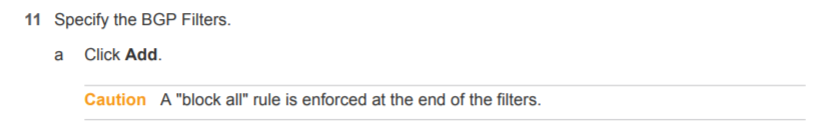
So, when you add a filter of any kind, even a “Deny” one, you get a free “Deny/Block Any” thrown in! A big thanks goes to Wissam Mahmassani for helping me figure that little gem out! We don’t want to block everything else, just the two filters above, so we add this Permit Any rule to override the free Deny rule. Clicking OK and then “Publishing” the changes should be the last step.
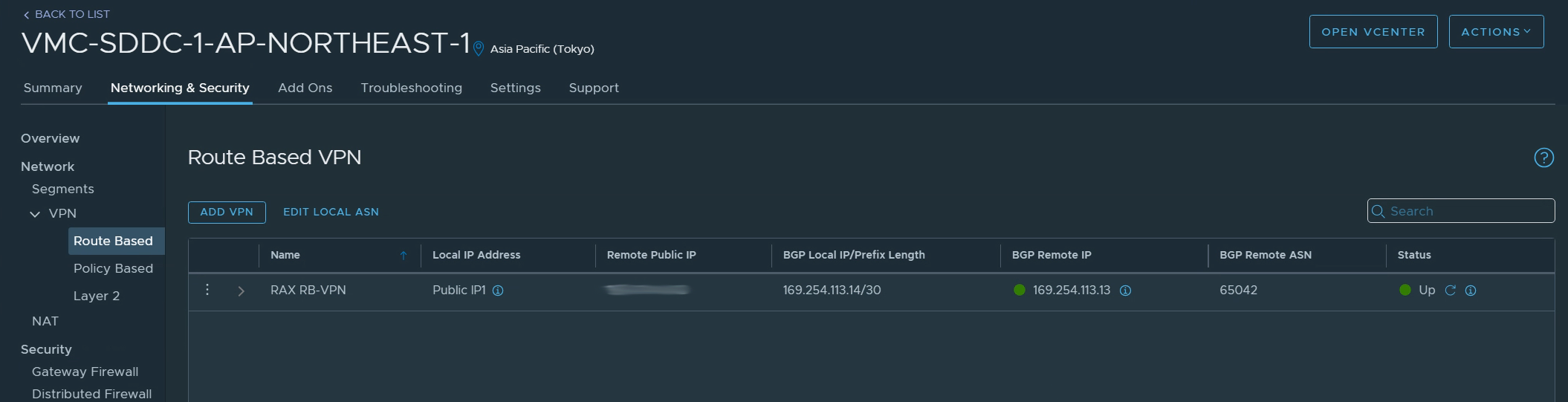
We can see how things look from the VMC end quite easily, and checking the VPN’s “BGP Remote IP” and “Status” fields show two nice green indicators.
Logging on to the SSH interface of the Edge allows us to check the status from that end too. Here are the three commands I used to make sure things look okay from there.
show ip bgp neighborswill give us a detailed breakdown of the err… BGP neighbors, and of course the status of our links with them.show ip bgp neighbor 169.254.113.14 routeswill show us the list of routes we’ve learned over BGP from that neighbour.show ip bgp neighbor 169.254.113.14 advertised-routeswill show us the list of routes we’re advertising to that neighbor.
And that is, (finally) it.
Summary
- Setting up the VMC end for either a Policy or Route-Based VPN is a matter of filling in the boxes with the appropriate values.
- It’s absolutely possible to set up a Route-Based VPN on an NSX-V Edge (v6.4.2 or above) but it’s more complicated.
- You create the VPN site using an API call to “PUT” a copy of the whole IPsec config, which includes the new site, into the Edge through the NSX Manager API.
- To create the config you “GET” the current config, add the details of your new site (watching out for gotchas) into the XML “body” of the response.
- Once the VPN site it created, you need to tell the Edge about its new BGP Neighbor, which you can do with the API, but we used the GUI.
- You then deserve a suitable beverage for all your hard work!
If you made it all the way down here, thanks for persevering! Hopefully you’ve found this post useful, or at least mildly interesting. If you have any comments or questions, please feel free to use the comments section below. I’d also like to give a big thanks to Daniel Paluszek and Sam McGeown for their help reviewing these posts!
Posts in this series:
- Route-Based VPN on an NSX-V Edge: Part 1 - Introduction
- Route-Based VPN on an NSX-V Edge: Part 2 - Deployment (this post)
Feel free to share this post...