
In Part 1 of this series we looked at the problem Cloud Providers and their customers face when accessing provider services over their Wide Area Networks (WANs). In this second post in the series we’ll explore a number of possible solutions. In some instances, services were designed from the beginning to face multiple tenant networks, each with possible overlapping address space. Where this is the case, we don’t really need to “design” a solution, just ensure that our service, and the connectivity model which connects our tenant WAN environments to it, follows the way the service’s designer envisioned it.
In some cases of course, this isn’t the case, and we need to hide the complexity of those overlapping customer networks from our service, so that we don’t confuse or scare it. We’ll look at both scenarios in this post.
Before we start, in Part 1, we carefully engineered our customers’ and the Provider’s networks so the service either worked, or, only exhibited one of the possible problems. This was done to introduce the issues in manageable bite-sized chunks. If you’ve read that post, you’re now, officially, an expert, so in this post, we’re (as Emeril used to say) kickin’ it up a notch! In the examples in which we fix the various problems we identified in Part 1, we’ll take a worse case scenario where each of our tenants and the Provider networks all use exactly the same addresses. Buckle up, things are gonna get bumpy!
Don’t and say we did
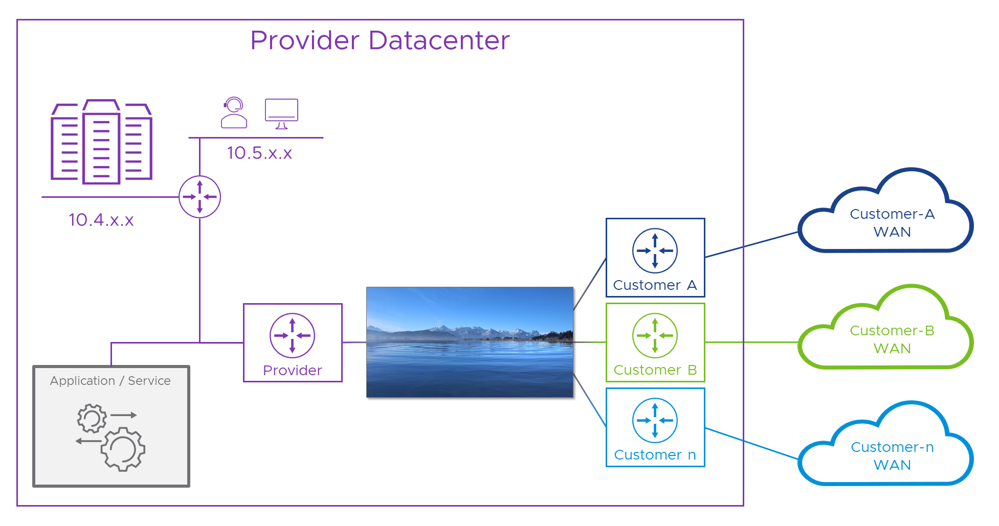
Sometimes, the best way to fix a problem is not to have it in the first place. Some software/hardware services are designed to face this issue without breaking sweat. The problem we’re going to fix exists because the services in question only have one, single, network stack. That means they have no way to differentiate between multiple addressing schemas which might also overlap. Where services are designed to cope, architecturally, the model is usually something like the one in the diagram below.
For clarity, we’ll move the “service” from that big stack of servers top left, to its own space in the middle of the diagram.
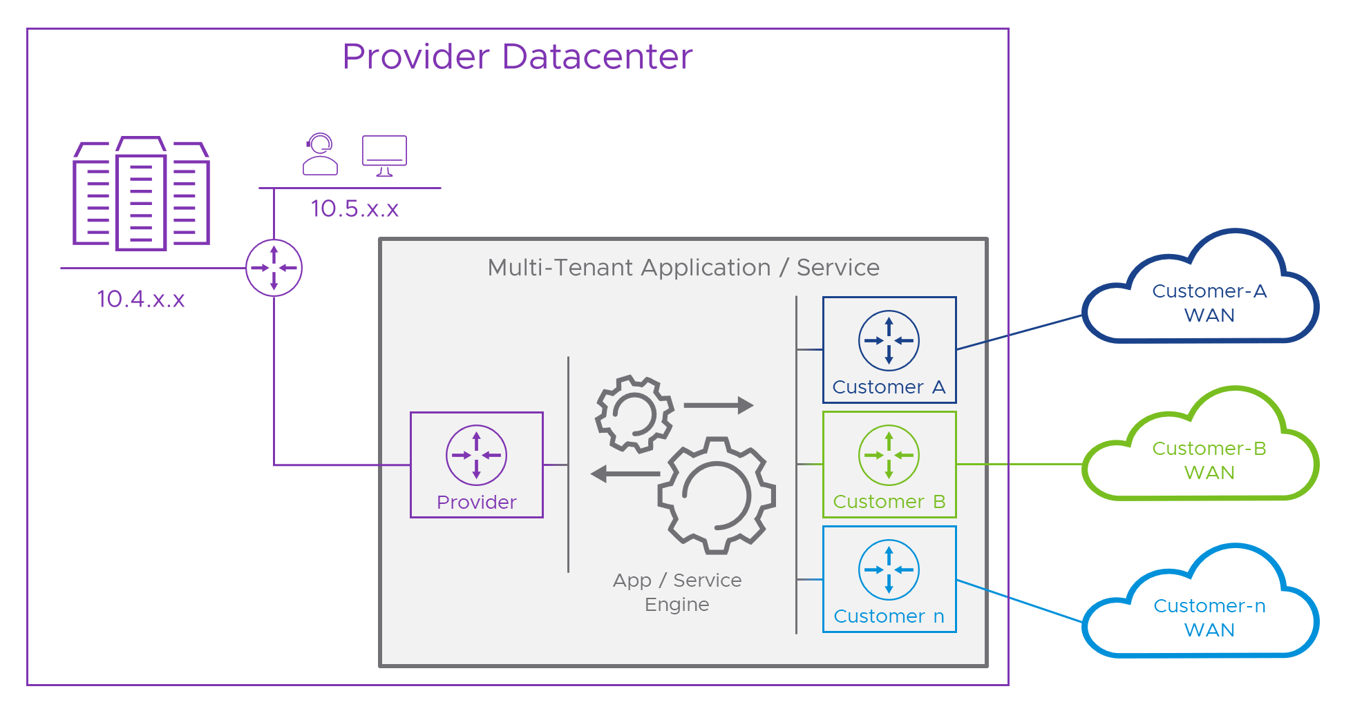
In the diagram, the dark box represents the natively multi-tenant service, for simplicity let’s call it an “appliance”. On its left hand side there’s a purple “router” which connects to the Provider’s network. This is an independent Routing and Forwarding base within the appliance, just handling traffic to and from the Provider. On the other side, there’s a similar setup, but in this case, one for each customer. In between the two, and here’s where the magic happens, the application itself runs in a network space which is independent of all of the connected networks. This part of the appliance can send and receive traffic to or from all of them, without being tied to the network addressing of any of the connected networks. Pretty clever stuff!
An alternative approach is to fix the issue at Layer 2 instead of Layer 3. Instead of using the packet’s source IP address to figure out how to route a reply, devices use the physical port that the connection came in through as the sign-post to the direction they should switch the reply back through. Usually in the Provider world this would be a L2 (datalink) interface with a VLAN ID to allow multiple connections on the same physical interface. A packet with source IP of 10.1.1.1 on VLAN 101 would be returned over VLAN 101 whereas one with the same source which came in on VLAN 102 would be returned over that VLAN and so on. F5’s BigIP “Auto Last Hop” feature is an example of this (although F5 KC Article K55225090 suggests support for this, at least in VE is something you should check against the version you’re running).
The main challenge we’re working so hard to overcome is when more than one network uses the same addresses as another. In Part 1 we saw that, although a bit more dangerous, the Internet doesn’t add to this overlapping address malarkey. This means that we don’t necessarily need another “Internet router” inside the appliance, instead, we can bring in the Internet through the Provider side as we saw in Part 1. To save you flicking back to that, here’s what that would look like if we add it to the previous diagram.
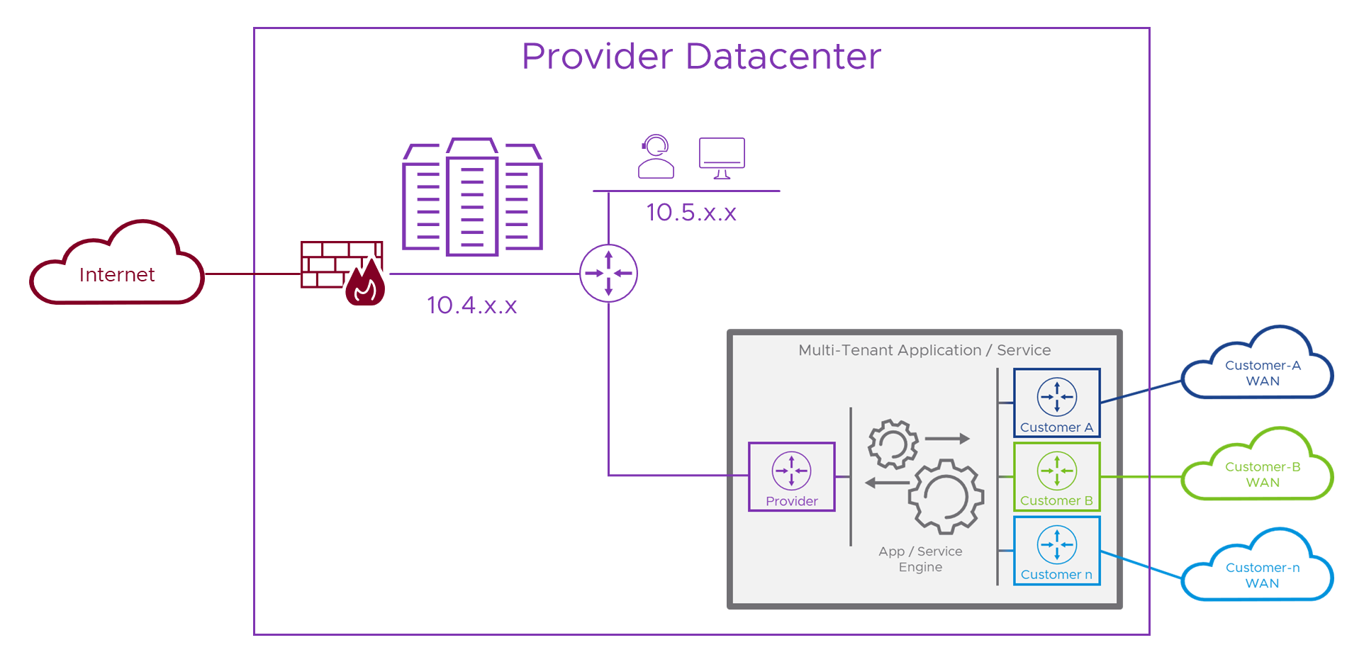
Internet access and the Provider networks don’t clash, so we can deliver them both to the appliance on the same interface. In practice, this would be the Provider’s networking specifically to do with delivering these types of services to the Internet, complete with firewalls, IDS, IPS, etc. and not all of their corporate IT networks or other sensitive parts of their infrastructure.
Okay, so that’s what the problem looks like in a solution where we err… don’t actually err… have the problem. Say what? Actually, although seemingly a bit weird, that’s no bad thing, as we now have a model that we can use to build our own solution against.
Not so lucky
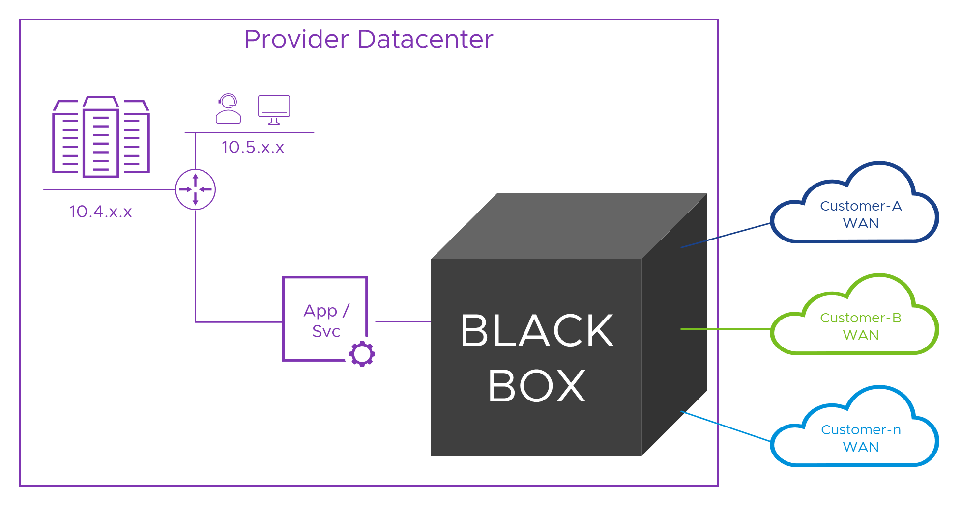
It’s no help knowing that some services don’t have the problem if the service we have does. Actually, more often than not, services designed for the Internet or to be deployed to a single network will need help to operate in our multi-tenant Provider world. Typically, this means we need to connect the service to a network which doesn’t suffer from this problem, and then, do the same for each of the connected customers WAN networks. Easy! Here’s a diagram representing the solution (and I bet you were expecting another looooong NT.B post right?).
Inside the black box
When we need to fix the problem ourselves, Network Address Translation (NAT) is the usual go-to tool we reach for when we need to hide one network from another. “Just use NAT!” is a phrase which you can use to identify a real network engineer. Say that to them, and if they look like they just swallowed something really unpleasant, they’re a network engineer! There’s a maxim that holds true most of the time which is “Route if you can, NAT if you must”. Sadly, in this case we must. There are many explanations of NAT on the Internet (like the one in the link above), but for our purposes, NAT takes an IP packet with a Source and Destination address and port number, and lets us swap some, or all of them, for new values, usually following some rules that ensure we can keep track of what’s going on. We can swap the source, destination or, in some cases, both, addresses and/or ports.
Let’s take a look at the flow from the first tenant, over their WAN, to the Provider’s service. Fair warned, this time, we’re going to change the addresses so that the customer is using the same addresses as the Provider. As the song says, if we can make it [work] here, we can make it [work] anywhere! Alice from Customer-A has been promoted, she’s now in err.. Another Department and has a new PC whose IP address is ‘10.1.1.1’. Over in the Provider network, the new portal is live and, on the Provider’s network its IP address is also ‘10.1.1.1’. If we were to color-code them for clarity, Alice has an indigo ‘10.1.1.1’ whereas the Provider portal is a plum ‘10.1.1.1’ .
Colors help us, but sadly IPv4 is color-blind and can’t tell them apart. That means, Alice can’t target the portal’s real address. She has to connect to an address which makes sense on her network and doesn’t clash with her or anyone else’s address on her network. We’ll need to ask the Customer A network admins to allocate some addresses which we can use to represent the Provider services in the customer network. Let’s say they give us ‘10.2.2.x’ (‘10.2.2.0/24’) and from that we choose ‘10.2.2.2’ for the portal. So now, Alice can connect to that and, (as we learned in Part 1, with the help of network engineers and a good Project Manager) we’ll then route her traffic to the Customer-A router within the Provider’s DC. As each packet flows through that router, we’ll translate the “destination” address field (DNAT) in the packet from ‘10.2.2.2’ to ‘10.1.1.1’ . We’re not finished yet, but let’s see what that looks like so far.
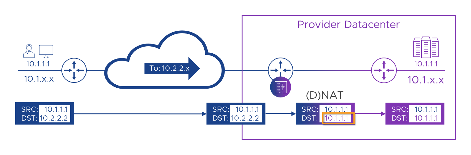
So far, so good! We’ve managed to route a packet from Alice to the portal, swapping colors.. I mean addresses (using ‘NAT’) as we go. We’re currently NATing on the Customer router in the Provider’s DC, as we need to translate the packets while they’re still in the context of that customer’s WAN. If we try and manage the NAT on the single plum-colored Provider router we’d have probably lost the customer context before we got around to NATing anything. However, if you read Part 1 and are now an expert, you may spot a slight flaw in our otherwise awesome plan. Currently, although we’ve made it possible for Alice to send a packet (or more than one) to the Portal, when the packet gets there and we want to try and reply to it, the Source address the packet came from is still Alice’s indigo ‘10.1.1.1’ . we’ll look to fix that in a moment, but before we do, there’s another, slightly more hidden problem in what we’ve got so far. This sneaky issue is going to try and bite us in a few places, so it’s worth beating it into submission with a stick now, before it gets out of hand…
Orders are orders
Most network devices perform a mixture of roles. Routers are optimized for routing packets and managing the protocols that allow learning of network routing topologies, but, they can also filter packets (like a firewall) and NAT them too. Firewalls may be optimized for complex filtering rules or traffic analysis, but can also route and NAT too. What’s common to all of these devices is that they will each have a specific sequence or ‘order’ in which the steps are carried out. Take our NSX-T Edges for example. Traffic flowing from outside to inside is first NAT’d, then subject to firewall rules and finally forwarded (routed) towards its next hop/destination. But, on the way back, the packet is first filtered (firewall rules), then NAT’d and finally forwarded. Different direction, different order!
Let’s see that NSX-T order of operation laid out more clearly.
[Outside] NAT Filter (Firewall) Forward (Route) [Inside]
[Outside] Forward (Route) NAT Filter (Firewall) [Inside]
Taking this as an example, if we were using one of our NSX-T T0/T1 Edges to perform the job of the tenant WAN router in the diagram, it would take the packet, translate (NAT) the destination from ‘10.2.2.2’ to ‘10.1.1.1’ then it would check its firewall rules to see if the packet is allowed (we’ll assume it is) and then try and route the packet to ‘10.1.1.1’. But, err… which ‘10.1.1.1’? It now has one on each side!
If the order of operation where route first and then NAT, we would decide the packet was heading (being routed) out towards the Provider Router (which we’re still pretending is ‘10.2.2.2’ ) first, then, once we’d decided which interface to send the packet out of, we’d swap the destination to ‘10.1.1.1’ and away it would go towards the portal. As we’re working on a worse case scenario here, we’re going with the router in our diagram NATing before it routes, and that means we can’t simply NAT to the Portal’s ‘10.1.1.1’ address because that address (without the pretty color) also exists on Alice’s PC, which the router knows is in the opposite direction to the Portal. Aaargh!
So NAT is an awesome tool, but it works best where the addresses used on either side of the NAT-ing device can’t overlap. Like when we swap an rfc1918 address for a public Internet address when we connect to the some website on the Internet. In that case, we know that when we’ve swapped our address the new one will only exist on the inside or the Internet but not both. Here, NATing between potentially overlapping rfc1918 addresses is fraught with danger!
We’ll come back to that in a moment, but first let’s pretend for now that it’s not a problem, and look at the Provider trying to reply.
The right to reply
As we’ve engineered this to be the worse case scenario, when the Provider portal tries to reply to Alice, it will send from its address of ‘10.1.1.1’ to Alice’s… oh, wait, no! It can’t send to Alice’s ‘10.1.1.1’ because colors don’t count! We need to temporarily assign Alice an alternative address which is unique across the Provider’s whole network. We also need to have the routing devices know that whatever this address is, we should route it towards the Customer-A WAN router. Let’s just use some letters for now and call Alice ‘a.b.c.1’ . It’s okay for us to give Alice a temporary address so we can talk to her, but we need her to talk to us from this address first or we won’t know it’s her. This means we need to arrange to fix her incoming packets so they appear to come from her temporary address. Looks like we’ll need more NATs! Let’s take a look at that in a picture…
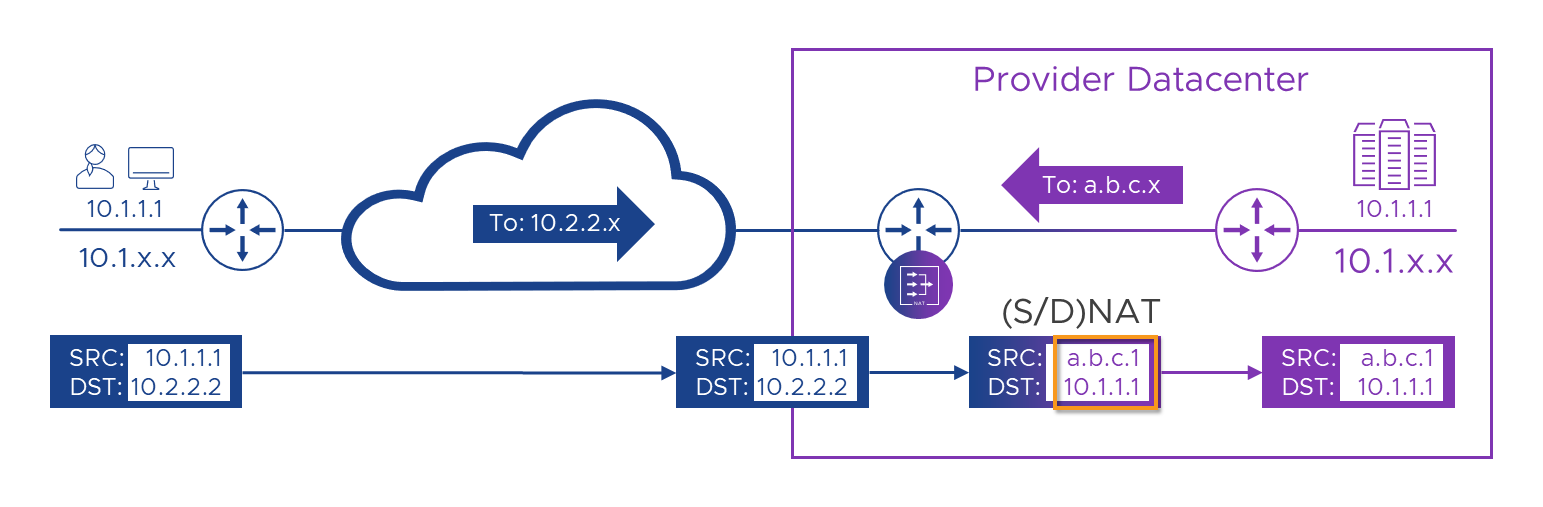
In the picture above, we’ve swapped Alice’s ‘10.2.2.2’ destination to the Provider’s real ‘10.1.1.1’ address, and we’ve also swapped her real ‘10.1.1.1’ source for the Provider-allocated ‘a.b.c.1’ address. We’ve also added a route to the Provider’s network which says that ‘a.b.c.x’ can be found through the Customer-A WAN router. Now that we’ve hidden Alice’s addresses from the Portal and vice-versa, we’ll get a flow which should look like this.
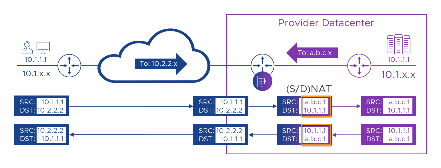
Let’s get real
It works on this diagram, but, because of the order of operation challenge, it won’t work in the real world. Let’s examine why. Here’s the diagram again, but this time with some handy-dandy numbers on (as we’ve spared no expense in this post!), to help guide us. Even when things fail, we’ll ignore that and carry on, as that will give us a list of things to fix.
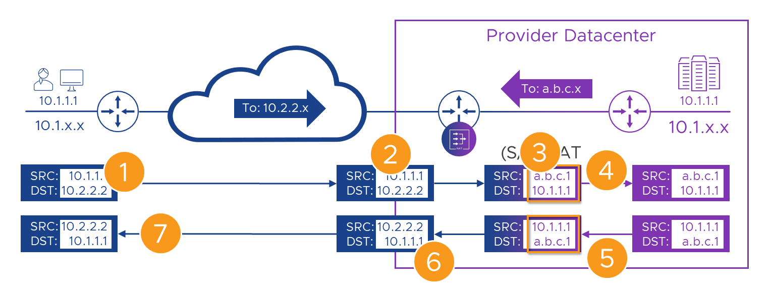
Here’s the flow, step by step. Remember, even when things break, we’ll carry on as if they didn’t.
| Step | Action | Result | State |
|---|---|---|---|
| 1 | Alice connects to her WAN’s address for the portal - ‘10.2.2.2’. | The packet with the original addresses in is sent over the WAN. | |
| 2 | The packet, still with its original source and destination addresses arrives at the Customer-A WAN router | The packet is passed to the NAT engine in the router | |
| 3 | On it’s way through the router we swap (NAT) Alice’s source and the Portal’s destination addresses | The translated packet needs routing to the new 10.1.1.1 destination, but that exists on both sides of the router. | |
| 4 | The translated packet is forwarded to the Provider router with it’s new source and destination addresses | The packet is routed to the portal. | |
| 5 | The portal builds a reply packet using its own address (source) and the Alice’s ‘a.b.c.1’ address from the received packet (destination). | The packet is forwarded to the Customer-A WAN router because of the route we added to the Provider router | |
| 6 | On it’s way back through the Customer-A router, the packet has its source swapped to the ‘10.2.2.2’ address Alice knows the Portal by, and its destination to Alice’s real ‘10.1.1.1’ address. | Like in [3] we need to route to ‘10.1.1.1’ but again, we have one on each side of the router. | |
| 7 | The packet is delivered back to Alice’s ‘10.1.1.1’ address, apparently from ‘10.2.2.2’ | The rest of Alice’s connection follows the same sequence |
On reflection, we did pretty well and almost got it to work. Let’s look at what’s still on the glitch-list.
- [3.] We can’t NAT Alice’s packet’s destination address to the real address of the Portal because that address exists on both sides of the NAT-ing router.
- [6.] We can’t NAT Alice’s temporary destination address to her real address for the same reason as [3.] above.
- [5.] (and [.3]) we need some sort of schema for allocating temporary addresses, potentially to lots of devices from lots of customers and to multiple Provider devices too.
(Either that or wait for IPv7 and see if it supports Hex, Alphabetic or even colored addresses!)
We have a dog, a cat, a mouse and a rowing boat
Remember here where we said that NAT was awesome as long as the same address(es) didn’t exist on more than one side of a NAT device ? Well, therein lies the secret to fixing this! A bit like the per connection routers in the black box example, we need each of the networks to be completely independent of the others. We need a sort of “no mans land” in the middle (like the lake in Harry Potter VI but without the lurking nasties), and we need to know how to cross it safely and get back. Kind of like this.
You see here, packets arriving at the lake’s shore are more worried about getting their bits wet than what’s on the other side. While they’re in a state of panic, we can NAT them to some “lake” addresses (don’t worry, I’ll get bored of the water metaphor soon). Just like the earlier case where we gave Alice a temporary (‘a.b.c.1’) address to ensure she didn’t clash with anything on the provider network, here, we’ll assign her (and anything else from the Customer-A WAN) a “Customer-A lake” address like ’la.ke.A.1’, so she doesn’t clash with anything else. We can also allocate the Provider a bunch of “lake” addresses to use for each of their components or services which customers will need to reach.
When a packet leaves its origin, say Alice’s PC, it will still need source and destination addresses which make sense on the Customer-A WAN. Let’s say Alice’s ‘10.1.1.1’ and the Portal’s ‘10.2.2.2’ . We shouldn’t need Alice or her network engineer’s (or their PM) to know about the scary lake, that nightmare lives in the Provider space but we do need to Source and Destination NAT (SNAT/DNAT) the packet somewhere, so we’ll need a Provider-side Customer-A NAT device of some sort. There, we’ll hide Alice’s address behind a “lake” address and, we’ll see which of our services she wants (oh, it’s the Portal again) and swap her ‘10.2.2.2’ destination for the portal’s “lake” address. Now the packet is safely wrapped in “lake” addresses we can forward it across to the Provider’s side of the lake.
When the packet reaches the Provider’s side, we’re going to need more NATs, and, something to do the NAT-ing. This something will take the destination (“lake”) address and swap that for the portal’s real address in the provider network ( ‘10.1.1.1’ ). We can then decide to either leave Alice’s “lake” source address and have the Provider network route all lake addresses back to the err… well lake. Or, we can also NAT Alice’s lake source to a Provider-allocated rfc1918 address. Why go through this additional, and seemingly pointless step? Well, it depends on the range of addresses we choose to fill our lake from. We’ll look at that choice shortly. In the meantime, here’s a schematic of our solution so far.

We still need a WAN “Customer Edge” (CE) router for each customer (that’s part of their WAN service) and we might be able to use that for some of the NATs, but erring on the side of caution, we’ve got a WAN <-> Lake NAT device for each customer, and one for the Provider, all managed by the provider. Here’s our Packet walk again, this time with the lake in it.
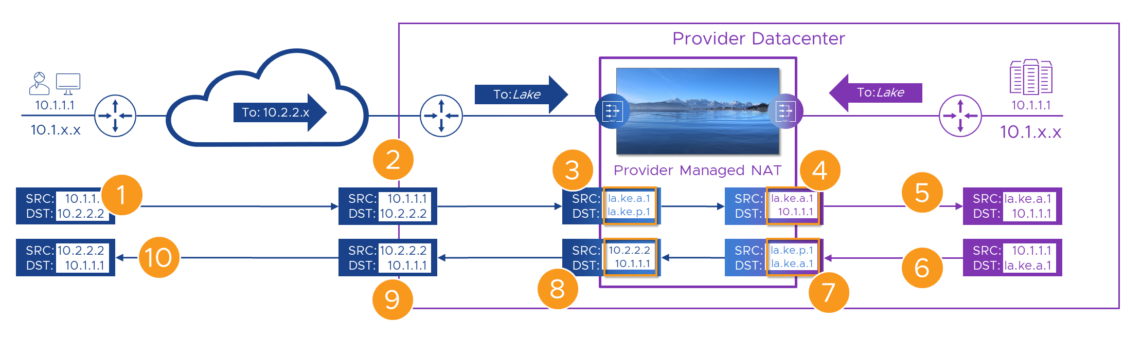
Here’s the flow again, step by step. Fingers X’d that nothing breaks this time!
| Step | Action | Result | State |
|---|---|---|---|
| 1 | Alice connects to her WAN’s address for the portal - ‘10.2.2.2’. | The packet with the original addresses in is sent over the WAN. | |
| 2 | The packet, still with its original source and destination addresses arrives at the Customer-A WAN router | The packet is passed to the Provider managed “Customer-A” NAT engine | |
| 3 | On it’s way through, we swap (NAT) Alice’s source (to ’la.ke.a.1’) and the Portal’s destination (to ’la.ke.p.1’) addresses | The translated packet needs routing to Provider portal’s “lake” address which only exists on the other side of the lake. | |
| 4 | The packet has its destination NAT’d to the real ( ‘10.1.1.1’) address of the portal | The packet is forwarded towards the portal. | |
| 5 | The packet’s source and destination are unique within the Provider network | The packet routes correctly to the portal | |
| 6 | The portal builds a reply packet using its own address (source) and the Alice’s ’la.ke.a.1’ address from the received packet (destination). | The packet is forwarded to the Provider NAT engine because of the route we added to the Provider router | |
| 7 | On it’s way back through the Provider NAT engine, the packet has its source swapped to the portal’s ’la.ke.p.1’ address. | As in [3] Alice’s ’lake’ address now only exists on one side of the lake so the packet routes back correctly. | |
| 8 | Before we send the packet back to the Customer-A WAN we need to get rid of all this ’lake’ stuff, so we NAT both source and destination addresses | Once the packet has Customer-A WAN addresses again, it can be sent to the Customer-A WAN router in the Provider DC | |
| 9 | As the packet has Customer-A WAN addresses again, it can be forwarded back to Alice | With Alice’s real destination address, the packets route correctly to her site on the WAN | |
| 10 | The packet is delivered back to Alice’s ‘10.1.1.1’ address, apparently from ‘10.2.2.2’ | The rest of Alice’s connection follows the same sequence |
So, this time we made it all the way to the end of the flow without a single ‘’ - Woohoo! If we can find some addresses to replace the stupid lake metaphor, we’ll be able to build a real solution. When we do that, we should also stress test it with Bill over at Customer-B who, as you might have guessed also has a new computer and his IP address is, of course, ‘10.1.1.1’ !
If you read that and it all sounds familiar (or if you skipped it and just want the TL;DR), that’s because it is. If Alice connected to the Provider’s portal over the Internet we’d see exactly the same process. Don’t connect two rfc1918 networks together, that’s like crossing the streams. Instead, we connect from Alice’s private network to the Internet at one end, and back to the Provider’s private network on the other. The subtle difference is that in this case, Alice simply targets the Internet address (via DNS lookup of the portal domain name of course) directly. She doesn’t have to connect to a fake internal address to force the connection over the Customer-A WAN. But, other than that, it’s a very similar model.
It’s a wrap
Go us! - We made it work. Let’s recap where we’ve got to and take a moment to let our headaches calm down before we head off to Part 3. In this post, we’ve finally managed to get a packet from a customer device (Alice’s PC) all the way to the Provider portal even though they both had the same IP address. We worked out that although NAT was part of the solution, you can’t safely NAT between two networks connected to the same device unless (as it the case with your network and the public Internet), the two networks do not have any overlapping addresses. We learned that this was in part because there’s the potential for a device to NAT first, and then route/forward, and this breaks when the new address exists somewhere on both sides.
Finally, we were subjected to that stupid lake metaphor to illustrate that NAT will work as long as we go from Customer to unique addresses first, then unique addresses to Provider (or vice-versa). In this way, isolating both Customer and Provider networks from each other (with the ’lake’ addresses) stops NAT from trying to bite us. All we need now is a practical example that we can use to do this in the real world, and to see if it will work when: No_of_Customers > 1.
Let’s keep our fingers crossed that all of that turns up in Part 3!
- Multi-Tenant WAN Access to Shared Resources: Part 1 - The Problem
- Multi-Tenant WAN Access to Shared Resources: Part 2 - A Solution (this post)
- Multi-Tenant WAN Access to Shared Resources: Part 3 - Real Numbers
In case you were wondering, that's around 4097 words of your life you'll never get back..!
Feel free to share this post...
See also
- Multi-Tenant WAN Access to Shared Resources: Part 1 - The Problem
- Multisite vCloud Director With Global Load Balancing
- Cross OrgVDC Networking in vCD 9.5