With the introduction of NSX-T as the Software Defined Network (SDN) layer in VMware Cloud on AWS ("VMC") we gained the ability to create both traditional “Policy-Based” and the less common but arguably more powerful, “Route-Based” VPNs. Although some planning and design is necessary for either type of VPN between VMC sites, the actual configuration is quite straight forward. Fill in the fields on the SDDC console, click “Save”, repeat for the other site and you’re done. However, if the “other” site is not a VMC SDDC but instead an “on-prem” location running NSX-V, and you’re setting up a route-based VPN, things get a little more complicated. In this post we’ll look at the differences between the two VPN types, and in the second post in the series we’ll go through the steps necessary to set up a route-based VPN on an NSX-V Edge Service Gateway (“Edge”).
Introduction
First, a little background. If you’re reading this post, you may already know the difference, but I’ll summarise it anyway, for completeness. If you don’t want the whole TL;DR back-story, click here to skip to the “how-to” post. Okay, lets have a look at the two different types of VPNs, first Policy-Based and then the focus of this series, Route-Based VPNs.
Policy-Based VPN
A policy-based VPN is logically comprised of two parts. You can think of the first, “outer” layer as an opaque pipe between the two endpoints of the VPN. You need to configure a local and remote IP address for the two endpoints, some encryption parameters, and a secret “key”. Configure the same parameters at the other end (reversing the “local” and “remote” details of course) and you’re half way there. The picture below shows these configuration elements in the VMC console.

Now that we have the opaque pipe between our two sites, it’s time to send some network traffic over it. You can think of this stage as adding some smaller pipes or tubes inside the outer pipe we just created. One limit with a policy based VPN is that there are no junctions, roundabouts or points in a railway track (pick your favourite transport metaphor) inside that outer pipe. In the config above we have two local networks which are both allowed to send traffic to each of two remote networks and this leads to four (two x two) of these inner pipes/tubes which are known as “Phase 2 tunnels”. Clicking on the “VPN Status details” link pops up an overview of the Phase 2 tunnels. As you can see in the image below, we’re looking at the fourth one here and can see just one local network connected to one remote network.

Two local networks connected to two remote networks isn’t a big deal, but imagine how this would quickly grow in a large enterprise with more local and remote networks to multiply together. Another pesky annoyance is that if we deploy a new network at one or other site, it wasn’t in the original policy, so there’s no Phase 2 tunnel and no traffic will be able to reach it until we add it to the configuration, at both ends! This challenge isn’t unique in the networking world. Wide Area Networks (without VPNs) face this same problem of learning about new networks, but overcome it with the use of a “Routing Protocol”. A routing protocol allows network routing devices to inform each other which networks they have access to, which in turn allows the whole network to build up a picture of what networks are where, and which routing devices can be used to reach them. Wouldn’t it be great if VPN devices could behave like routers and just learn what networks are reachable across their VPN tunnels? It sure would, so, enter the Route-Based VPN…
Route-Based VPN
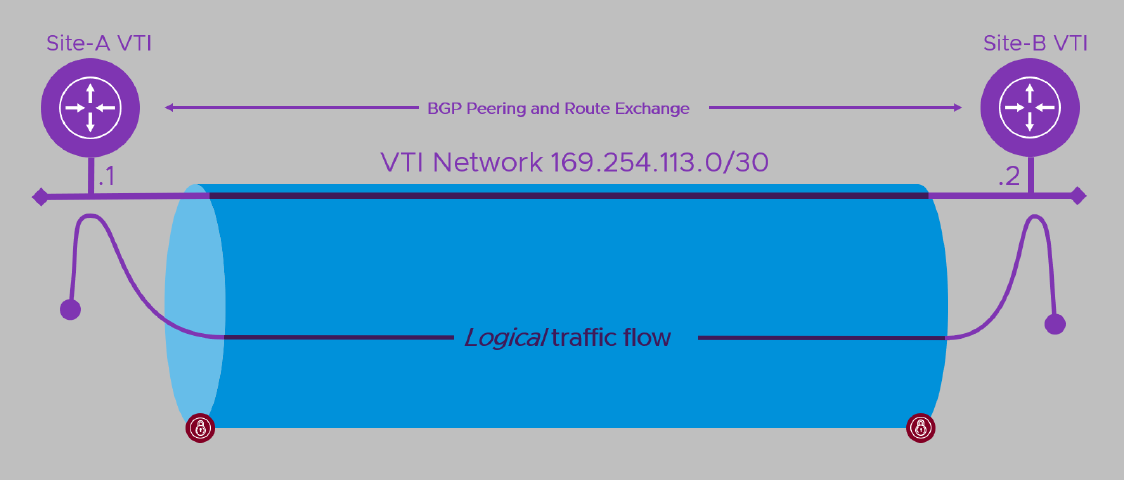
A Route-Based VPN shares a number of similarities with it’s policy-based cousin. First, there’s that “outer” opaque pipe with its IP address endpoints, encryption parameters and shared secret “key”. This time though, instead of lots of inner pipes you can visualise the outer pipe hosting a single connection between a virtual router at each end. The router is part of the VPN devices and is often referred to as a Virtual Tunnel Interface (“VTI”). The two VTIs need to be able to communicate in order to exchange information, so we have to create a logical network which spans the tunnel and give each VTI an address on that network. Ironically, the routing protocol used, (BGP in this case learn more ), needs the local and remote devices to be able to route to each other before they can exchange… err.. routes. The way we make that happen here is to put them on the same logical network (inside that outer pipe) as each other. We still need to tell each about its “peer” at the other end of the VTI network / tunnel when we configure the VPN though.
Here’s the diagram that I used at a recent event to explain the configuration elements.

Here the VPN device at Site-A on the left would be dynamically learning routes from Site-B and adding them to the VPN while Site-B would be doing the opposite. How traffic gets to the near end of the tunnel depends on the network topology.
- If the same device is also the Internet gateway for the local site, chances are all traffic will head towards it as it forms the default gateway from the network. When traffic arrives destined for the remote site, it’s sent towards the local VTI instead of over the Internet.
- If the VPN device is already providing access to other WAN locations (perhaps over MPLS, point-point circuit or another VPN), then it’s likely that all private (non-Internet, rfc1918) addresses will be sent towards it anyway. As above, traffic arriving destined for the remote site is sent towards the local VTI rather than to one of the device’s other links. In this and the previous case, the local device will tell the remote device about all the local networks it is directly connected to. It will also pass along the details of any other networks it is statically configured to reach internally.
- If the device is part of a complex, routed network of interconnected sites, as well as peering with the remote site, it can peer with a device in the local network. Through this, it learns of locally reachable address ranges (subnets/networks) and tells the local network which remote networks it can reach over its VPN connection.
In all cases, the local end will tell the remote peer which networks it has access to and, when traffic arrives at the local VTI destined for the remote network, it is forwarded to the remote VTI (over the wavy purple line above), where it then spills out into the remote site’s networks.
Summary
So, before we move on to the good stuff, let’s recap. Policy-Based VPNs have to have the networks they are to VPN between, configured in their policies. If the network world changes, the policies have to be changed too, or whatever has changed is ignored. Route-Based VPNs use a routing protocol (BGP) to tell their peer what networks they can reach, and then both use that information to configure which traffic should be sent through the VPN. When a VPN device learns of new networks, or old ones which are no longer reachable, it will tell it’s remote peer which will amend its VPN configuration to match the new topology.
All right, with the background covered, in Part 2 of this series we’ll look at the actual deployment of a Route-Based VPN between our NSX-V Edge and VMware Cloud on AWS. See you there!
- Route-Based VPN on an NSX-V Edge: Part 1 - Introduction (this post)
- Route-Based VPN on an NSX-V Edge: Part 2 - Deployment
Feel free to share this post...
